TEAMLINK3002 G.SHDSL provides multi stage line protection as per K.20 and K.21 with 2Wire operation with V35 interface, bandwidth of From 64Kbps to 2048Kbps
TEAMLINK3002 G.SHDSL provides multi stage line protection as per K.20 and K.21 with 2Wire operation with V35 interface, bandwidth of From 64Kbps to 2048Kbps
2 Wire Operation
Provides multi stage line protection as per K.20 and K.21.
Configuration Through DIP Switches.
External Secondary optional Line Protection Device
Long reach up to 11Kms. for standard 64Kbps speed
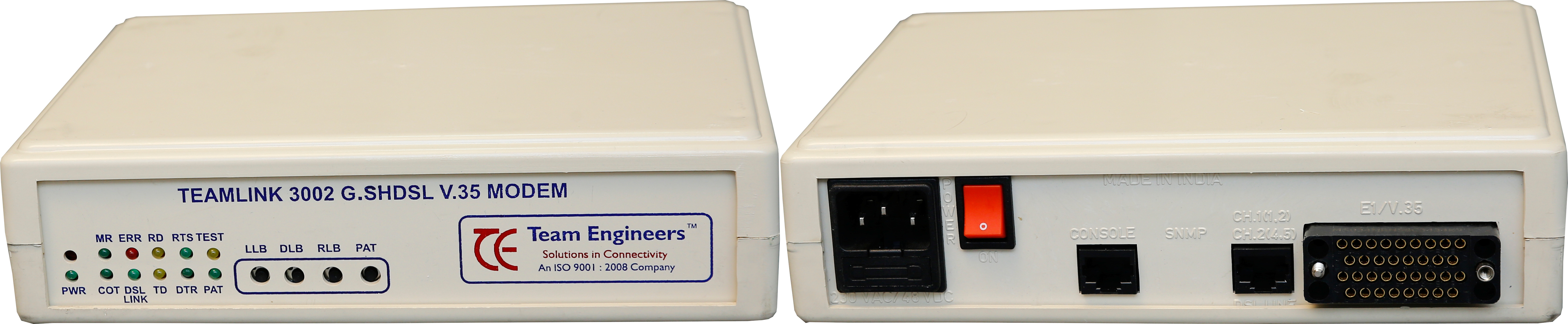
LED Indications for easy Monitoring
Front Panel Switches for Diagnostics or Loopbacks
Supports 230V AC and 48V DC with the Same Socket
Line type : 2Wire (single pair operation) twisted copper wire of 0.5mm Diameter.
Line Code : TCPAM as per the ITU-T G991.2 ( Annex –A and Annex –B ).
Bandwidth : Operates From 64Kbps to 2048Kbps
Line Impedance : 135 Ohms
Transmit Signal Power : 16 dBm +/- 0.5dBm
Operating Range : 6 Kms. on 0.5mm diameter copper cable @ 2.048Mbps data rate operation and 11Km on 0.5mm diameter copper cable @ 64Kbps in operation
Line protection : As per ITU-T K20 and K21
Transmit Level : Upto 16dBm
Connector : RJ 45
Surge Protection : Internal and Optional External Surge Protection
Interface : V35 .
Data Rates : 2.304 Mbps (n*64 Kbps, n=1 to 36) .
Transmit Clock Modes : Internal/External/Recovered from line
Connector : V35 Pin Female Connector
Configuration : Through DIP Switches
Clock Polarity Selection : RXCLK and TXCLK
Line protection : As per ITU-T K20 and K21
Transmit Level : Upto 16dBm
Connector : RJ 45
Surge Protection : Internal and Optional External Surge Protection
Local Loopback, Digital Loopback and Remote Loopback as per the ITU-T V.54 standard.
All loop back tests and BERT should be operated through Front Panel switches.
Built in test 511 pattern generation and checking (BERT) for the DSL Line as well as the PCM E1 Checking.
End to End Diagnostics and Status Monitoring is through the Embedded Operation Channel EOC without Interrupting the Data
Modem Configuration Through Dipswitches.
PWR, MR, COT, DSL LINK, DTR, RTS, PAT, ERR, TST
DUAL MODE AC/DC, 230VAC +/- 10% & –48VDC +/-10%
-5 To 60°C
Upto 95% non condensing
As per ITU K.20/K.21
s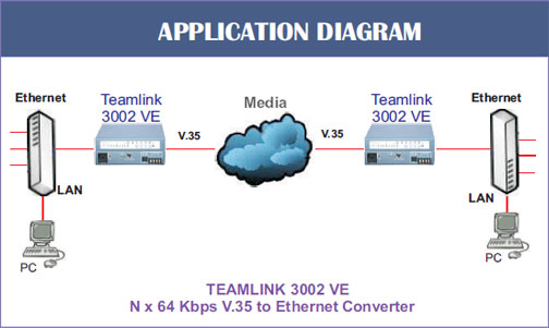
2 Wire Operation
LED Indications for easy Monitoring.
Supports 230V AC and 48V DC with the Same Socket
Line Impedance : 135 Ohms
Transmit Level : Upto 16dBm
Connector : RJ 45
Interface : V35
Data Rates : 2.304 Mbps (n*64 Kbps, n=1 to 36)
Connector : V35 Pin Female Connector